A deep-dive into one of the most underestimated risks in process plant design — and how to prevent it during FEED.
EXECUTIVE SUMMARY
Liquid pockets in flare headers are one of the most underestimated safety risks in process plant design. They form silently, corrode piping over years, and then — at the exact moment of an overpressure emergency — create slug flows that carry liquid to the flare stack. The result can be catastrophic. This blog breaks down the root causes, the real-world data, the regulatory requirements under API 521, and how to prevent this problem during FEED before it becomes dangerous and expensive.
1 Introduction — The Last Line of Defense
Every process plant has layers of protection against overpressure events: pressure controllers, high-pressure shutdowns, emergency depressurization systems. The flare system is the final layer — the one that activates when every other system has failed or been overwhelmed.
This makes the flare system uniquely critical. Its reliability is not just an engineering requirement; it is the difference between a controlled emergency and a catastrophic incident involving loss of containment, fire, explosion, and loss of life.
Yet, in my 23 years of working on EPC and FEED projects across Oil & Gas, Petrochemicals, and Mining & Metals, I have seen one particular design deficiency appear with troubling regularity — on existing facilities, and occasionally on new projects where it should have been caught in FEED.
That deficiency is the liquid pocket in flare headers.
It looks minor on a plot plan. It looks catastrophic in an incident report. This blog explains why — and what every piping engineer, process safety engineer, and PMC should be asking about on their next project.
2 What Is a Liquid Pocket — and Why Does It Form?
A liquid pocket (also called a liquid trap, dead leg, or piping sag) is a low point in flare header piping where liquid accumulates and cannot drain back to the Flare Knockout Drum (FKOD).
2.1 How Liquid Gets Into the Flare Header
Flare headers carry a mixture of vapor and liquid from relief devices across the plant. The composition changes significantly depending on the relief scenario:
- High-temperature rich hydrocarbon relief streams that condense as they travel through the header
- Water-containing streams (including sour water stripper relief) that condense in winter ambient conditions
- Condensation that forms after the main FKOD when driving pressure is low and vapor velocity drops
- Liquid carry-over from upstream relief devices under certain relief conditions
The FKOD is designed to knock out the bulk of liquid before it reaches the flare stack. However, a critical but often overlooked question is: what happens to liquid that condenses downstream of the FKOD?
If the flare header has continuous slope back toward the FKOD — as required by API 521 — this condensate drains safely. If not, it accumulates in low points. And once it accumulates, the risks compound over time.
2.2 The Three Danger Stages
Stage 1: Accumulation
Liquid pools in the low point of the header. This is not immediately dangerous, but creates ideal conditions for corrosion. Under-deposit corrosion, microbiologically influenced corrosion (MIC), and general corrosion from H₂S or CO₂ in the stream begin attacking the pipe wall. This phase can last months or years without detection.
Stage 2: Slug Formation
As the liquid level grows — or as a relief event creates high-velocity gas flow — the accumulated liquid is mobilized into slugs. These dense masses of liquid are accelerated by gas velocity toward the flare stack.
Stage 3: Liquid Carryover to the Flare Stack
This is the failure scenario. The flare stack is designed to burn vapor. It is NOT designed to handle significant volumes of liquid. When liquid reaches the stack, consequences can include mechanical damage to the stack structure, burning liquid rain falling around the flare, damage to the tip, and in severe cases, loss of containment at the base of the stack.
CRITICAL RISK
Liquid carryover to a flare stack during an active relief event — when the plant is already in an emergency overpressure condition — represents a compounding failure. The system designed to protect the plant becomes itself a source of danger.
3 Root Cause: FKOD Positioning and Header Slope
In the vast majority of cases I have reviewed, liquid pockets in flare headers trace back to one of two root causes — or both combined.
3.1 The Flare KO Drum Is Too Far From the Stack
The FKOD should be located as close as possible to the flare stack — ideally within 100 meters per API 521. When the FKOD is located at the process battery limit (sometimes 1,000+ meters from the stack), the header from drum to stack becomes a long unprotected run where condensation forms freely.
In winter conditions, with high wind velocities increasing heat loss, this condensation can be substantial. As the case study data demonstrates, this is not theoretical — it is measurable, quantifiable, and preventable.
✓ COMPLIANT DESIGN
< 100m
FKOD close to flare stack. Header maintains continuous slope. Condensate drains back safely to drum.
✗ NON-COMPLIANT DESIGN
> 1,000m
FKOD at battery limit. Long unprotected header run. Low points form. Liquid pockets accumulate.
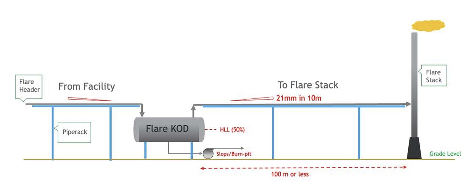
Compliant Design of Flare Header
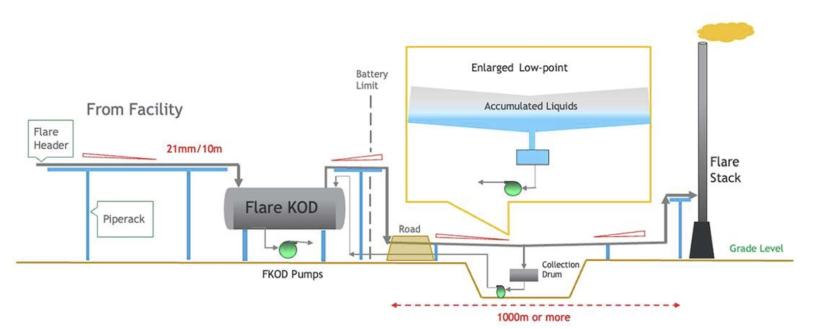
Non Compliant Design of Flare Header
Why do facilities end up with FKOD drums in the wrong location?
- The FKOD was positioned at the battery limit to minimize piping run costs within the process area
- Brownfield facilities where the flare stack was added or relocated after the KO drum was already installed
- Cost-driven FEED decisions that traded capital expenditure savings for long-term operational risk
- Insufficient flare system expertise on the FEED team at the time of plot plan development
3.2 Inadequate or Lost Header Slope
API 521 specifies a minimum slope requirement of 21mm in 10m (0.25 inches per 10 feet) for all flare laterals and headers, directed toward the FKOD. In practice, maintaining this slope across a large facility is more challenging than it appears:
- Pipe support decisions made to reduce structural steel cost can create local low points
- Pipe rack level changes — for road crossings, cable rack crossings, or equipment clearances — create elevation changes
- Brownfield routing decisions that work around existing obstacles often compromise the slope profile
- Insufficient attention to slope verification in the 3D model during detailed engineering
- Sagging between pipe supports in a sloped line leading to local pocket formation
API 521 REQUIREMENT
Slope: 21mm in 10m (0.25 in. per 10 ft) must be maintained on all laterals and headers, directed toward the FKOD, to ensure condensate drains back to the knockout drum and does not accumulate in low points.
4 Real-World Case Study: The Numbers That Should Alarm Everyone
A detailed technical analysis was conducted by engineers from Saudi Aramco and Siemens Energy on a low-pressure (LP) flare header system at an existing facility, using AspenTech’s Aspen Flare System Analyzer. The study is documented in the paper “Flare system design: Liquid pockets in flare headers” published in Hydrocarbon Processing.
| Parameter | Value |
|---|---|
| Header diameter | 76 inches |
| Header length — FKOD to flare stack | 7,741 ft (2,359 m) |
| Insulation / heat tracing | None |
| Existing collection drum capacity | 1,220 ft³ |
| Automated liquid removal | Not provided |
4.1 Case A — Condensation During Relief
All applicable overpressure scenarios were simulated at three wind velocities (32, 15, and 3 ft/sec). The governing scenario was total power failure at 15 ft/sec wind velocity:
2,538 ft³
Condensate formed during total power failure (governing case, 15 ft/sec wind)
158,570 lbs
Liquid mass collected in 20 minutes (operator response time assumption)
1,220 ft³
Existing collection drum capacity — less than 40% of what was required
8 min
Time to vessel overfill from low-low level to top — in an active emergency
4.2 Case B — Condensation at End of Relief
A second analysis estimated condensation after the relief scenario ends. When relief flow stops, remaining vapor condenses as pressure equalizes. The end-of-relief condensate volume was calculated at 492 ft³.
The Case A (during-relief) volume was the governing case. With a 20% design margin, the required collection vessel volume was 3,045.6 ft³ — compared to the existing 1,220 ft³.
THE CRITICAL GAP
The existing collection system had less than 40% of the required capacity, with no automated liquid removal. In an active overpressure emergency — with operators managing multiple simultaneous alarms — the window for manual intervention was 8 minutes. That is not a margin. That is a liability.
5 The Engineering Solution: Three Pillars of Compliant Design
Preventing liquid pocket formation and managing condensate safely requires addressing three engineering pillars — and all three must be addressed during FEED, not in detailed engineering, not in construction, and certainly not in operations.
Pillar 1: Correct FKOD Positioning
The FKOD must be positioned within 100 meters of the flare stack. This single decision has more impact on flare header integrity than any other. For existing facilities where the FKOD cannot be relocated, the team must acknowledge the risk and implement compensating measures — specifically a properly sized and automated liquid collection system at all identified low points.
Pillar 2: Maintaining Continuous Header Slope
The API 521 slope requirement of 21mm per 10m must be verified in the 3D model during detailed engineering and confirmed by survey during pre-commissioning. Where slope cannot be maintained due to physical constraints, low-point collection vessels must be added — not the slope deviation accepted.
Pillar 3: Properly Sized and Automated Liquid Collection
Where low points exist — particularly in brownfield facilities — a dedicated liquid collection system is required. Key requirements:
- Sizing: Based on hydraulic simulation of all governing relief scenarios. Apply a minimum 20% design margin. Size for 20-minute operator response holdup time.
- Automation: Motor-operated pump or automated dump valve — manual operation is NOT acceptable
- Instrumentation: LLL alarm to initiate pump start; HLL and HHLL alarms connected to DCS
- Redundancy: Lead-lag pump arrangement (two pumps) — one primary, one standby
- Discharge destination: FKOD, slops, closed drain, or burn pit
DESIGN PRINCIPLE
Absence of automated instrumentation poses a significant risk. Manual operation, by its very nature, is prone to human error — particularly during emergencies when operators are responding to multiple simultaneous alarms. Any malfunction or delay in automatic liquid removal could lead to liquid carryover to the flare stack.
6 The FEED Imperative: Why This Must Be Solved Early
The problems described in this blog are almost always visible — and fixable — during FEED. The FEED stage is where plot plans are established, where the FKOD location is decided, where header routing is first sketched, and where the piping design basis is written.
Once a project moves into detailed engineering, the cost of changing FKOD location, rerouting a major flare header, or adding an unplanned collection vessel can trigger significant change orders, schedule delays, and in some cases, the kind of value engineering decisions that leave safety risks in place.
FEED Checklist for Flare Header Liquid Pocket Prevention
| FEED Action | Description |
|---|---|
| FKOD Location Review | Confirm FKOD is within 100m of flare stack. If not achievable, document the gap and plan compensating measures. |
| Plot Plan Slope Review | Verify that the header routing from each lateral to the FKOD can achieve and maintain 21mm/10m slope with no unavoidable low points. |
| Condensation Analysis | Commission hydraulic simulation for all governing relief scenarios at multiple ambient conditions (high, medium, low wind velocity). |
| Collection System Sizing | Size the low-point collection vessel based on the governing condensate volume (Cases A and B) plus 20% design margin. |
| Automation Specification | Specify automated liquid removal with LLL/HHL instrumentation, DCS integration, and lead-lag pump redundancy. |
| Inspection Program | Define a dead-leg inspection program for any existing low points, including NDT methodology and corrosion monitoring locations. |
7 Existing Facilities: Managing the Risk You Already Have
For engineers working on existing facilities with non-compliant flare header orientations — and there are many — the challenge is managing the risk that already exists while working toward long-term remediation.
Inspection and Integrity Management
All suspected low-point locations must be incorporated into the facility’s onstream inspection program as dead-leg circuits:
- Identify all suspected low-point locations using survey data and 3D model review
- Apply non-destructive testing (NDT) — typically ultrasonic thickness measurement — at regular intervals
- Establish corrosion monitoring locations for longer piping circuits
- Set minimum remaining thickness acceptance criteria and plan pipe replacement proactively
Collection System Adequacy Review
Any existing low-point collection vessel must be reviewed against condensate volumes from hydraulic simulation. If the existing system is inadequate:
- Increase collection vessel size to accommodate the calculated condensate volume plus design margin
- Retrofit automated pump systems with LLL/HHL instrumentation and DCS integration
- Add lead-lag pump redundancy to the liquid removal system
- Conduct functional testing of all instrumentation before the next plant start-up
8 Key Questions for Engineering and PMC Teams
Whether you are a piping engineer designing a new facility, a process safety engineer reviewing an existing plant, or a PMC evaluating contractor FEED deliverables, these questions should be part of every flare system review:
- Where is the FKOD located relative to the flare stack? Is it within 100 meters?
- Does the flare header maintain 21mm/10m continuous slope toward the FKOD on all laterals and headers — with no unmitigated low points?
- Has a hydraulic simulation been performed to quantify condensate formation for all governing relief scenarios at multiple ambient conditions?
- Is the low-point collection system sized for the governing condensate volume plus a 20% design margin?
- Does the collection system have automated liquid removal with LLL/HHL alarms connected to DCS, and lead-lag pump redundancy?
- Are all identified dead-leg locations in the flare header included in the facility inspection program with appropriate NDT methodology?
Liquid pockets look minor on a plot plan.
They look catastrophic in an incident report.
The flare system is the last line of defense. A robust design is not optional. The cost of getting it right in FEED is a fraction of the cost of getting it wrong anywhere else. Make the right decisions early. Verify the slope. Size the collection system correctly. Automate the liquid removal. The plant depends on it.
References
1. H. Amin, M. Aldajani (Saudi Aramco, Dhahran, Saudi Arabia) and P. Dhote (Siemens Energy, Abu Dhabi, UAE). “Flare system design: Liquid pockets in flare headers.” Hydrocarbon Processing, Special Focus: Plant Design, Engineering, Construction and Commissioning.
2. API Standard 521, “Pressure-Relieving and Depressuring Systems,” American Petroleum Institute (current edition).
3. AspenTech Aspen Flare System Analyzer — Hydraulic simulation software referenced in the case study analysis.
Leave a Reply